ECE 4960: LAB 6 - Closed-loop Control (PID)
Description
With the robot now being able to be controlled via PWM commands, this lab extends the motor and driving functions of the robot by adding closed-loop PID control. This PID control uses depth information from the TOF sensor to bring more accuracy in the robot's motion.
1. Choosing a Task
The first step in this lab was choosing a task to be performed with PID control, as based on this task different code had to be written. For each of these tasks, we needed to ensure to log data to be able to plot and review the robot's behaviors, and also prepare for future labs where data export will also be required. I ended up choosing Task A: Don't Hit the Wall! which had as goal to stop the robot when it's 300mm away from the wall.
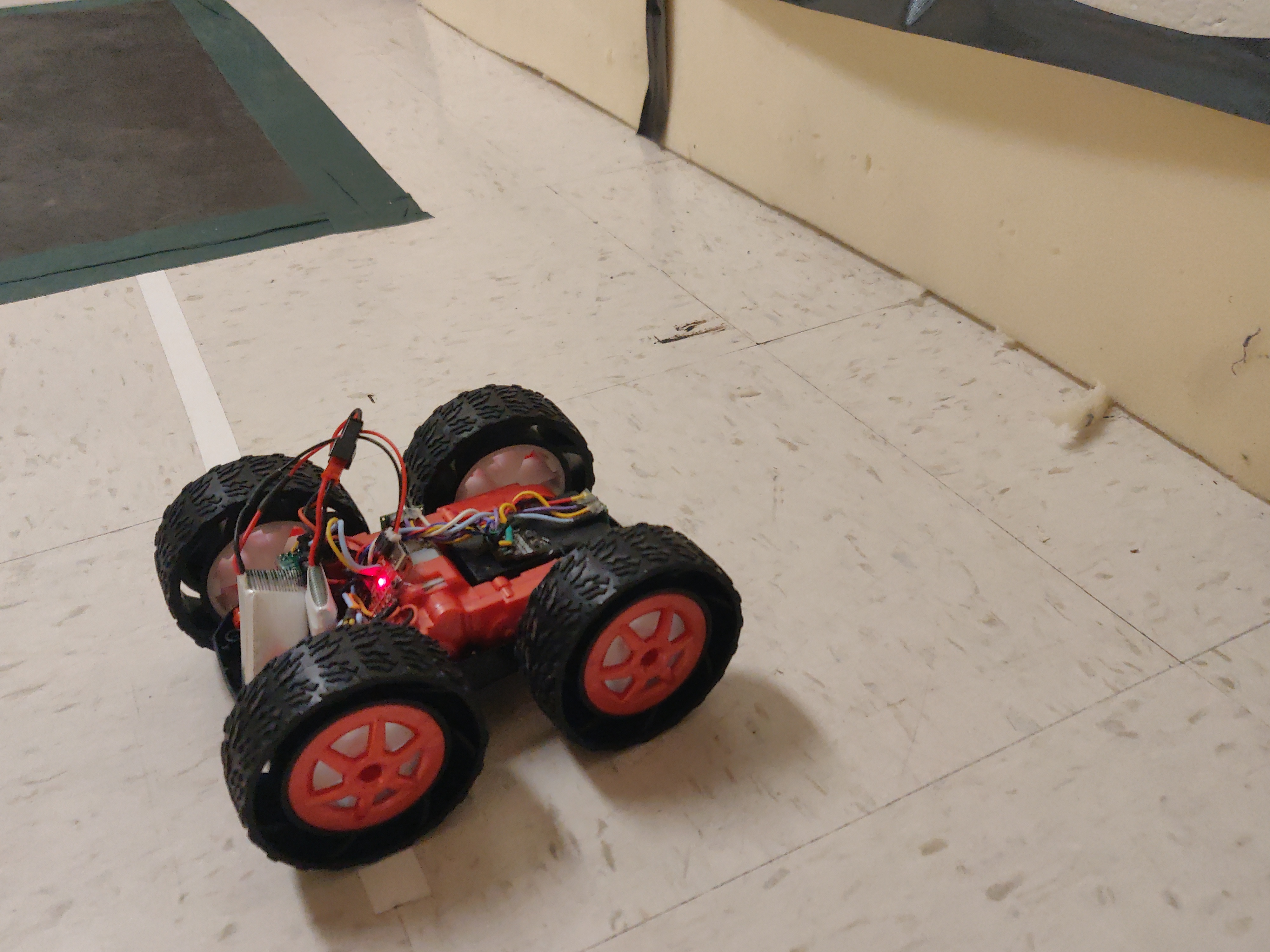
Figure 1: Task A: 300mm Stop in front of Wall
2. Designing the PID Controller
Given time contraints, i chose to focus on getting the P(ID) portion of the PID controller to work well. I had also heard from other people in the lab and from TA's that the robot performed well under just the P term of the PID controller, so decided to move forward with this.
For the P term of the PID controller, I calculated the difference between the distance from the goal and the desired distance (in this case 300mm), and once a value returned I multiplied the value by a gain value Kp. This essentially translated the distance different with gain multiplication into a control value for the robot - which is strongly dependent on the gain. This code is shown below:
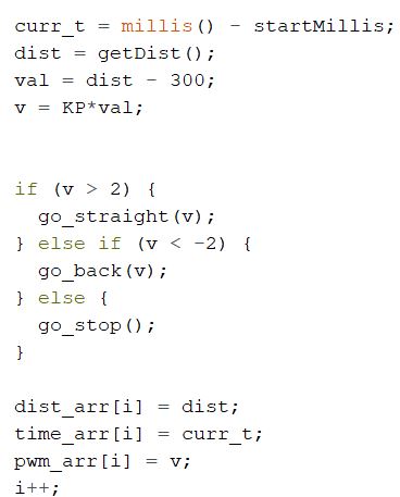
Figure 2: P(id) control code
In order to give the robot a range in which it was deemed reasonable to have reached its endgoal, the speeds at which the robot goes striaght or backwards were set between a range of -2 and 2, essentially allowing for it to stop moving if it's within a small margin of error.
3. Tuning the Motor Driver Functions for PID
Considering how the PID controller outputs positive and negative values, I had to go back and adjust my motor control code to deal with negative as well as positive inputs. I did this by simply converting any negative passed inputs to positive values (to the backwards function), assuming that a negative value passed to the backwards function simply is the output of a PID calculation. Additionally, I realized that the PID controller tended to output value above or below the maximum control values accepted by the robot (25 and 255). I therefore added code to convert any values above or below these to their respective maxima and minima. This is shown below:
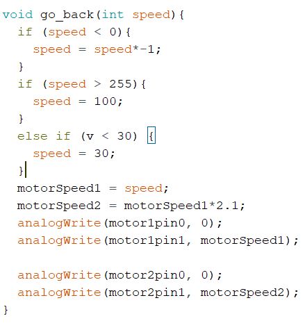
Figure 3: Motor Control Code
4. PID Experiments
This code was tested in the lab environment, and was found to repeatably result in accurate PID motion for the robot. The values used for Kp
ranged from 0.03 to 0.07, with 0.05 deemed to be the value delivering the best results. A further discussion below will compare plots
of each Kp value to determine any meaningful differences. Below, a PID run is demonstrated at a Kp value of 0.07, which is slightly too high resulting in a light tap of the wall.
The videos of the run at 0.03 and 0.05 unfortunately seemed to have been corrupted as I could not find them on my phone.
P(ID) Control with Kp 0.07
5. Discussion
Time vs. Distance
Data was collected over the runs at a gain value of 0.03, 0.04, and 0.07. Below are plots demonstrating the time vs. distance values for different Kp gain factors.
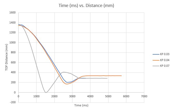
Figure 4: PID Control, Time vs Distance at various Kp values
What can be deduced from the below graph, is that a higher value for Kp does not necessarily result in the robot reaching its destination faster. In this case, the Kp of 0.07 overshoots the desired location significantly, and correct be undershooting, and eventually reaches the 300mm destination. On the other hand, the 0.03 and 0.04 factors do not overshoot nearly as much, leading to less back and forth motion before reaching the end-position.
Time vs. PWM
Data for PWM control values were also saved and plotted, resulting into similar insights:
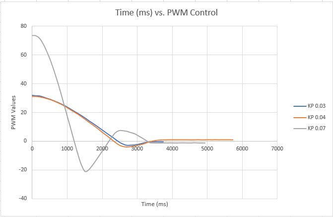
Figure 5: PID Control, Time vs PWM at various Kp values
Similarly, the PWM control values are far higher for a Kp of 0.07, resulting in a lot of overshooting and undershooting as the robot speeds up to fast and significantly misses its target, needing to correct. Kps of 0.03 and 0.04 on the other hand experience a smoother process towards the end-destination.
- - - - - This concludes Lab 6 - - - - -