ECE 4960: LAB 13 - Planning and execution (real)
Description
This final lab consisted of using PID control and localization to allow the robot to navigate along a fixed waypoint path in the lab map environment. I worked with a lab partner, Devlin, for this lab, and we decided on an approach relying heavily on PID control to accurately reach each waypoint. To avoid having the robot lose its orientation, we decided against executing localization at every waypoint, and instead only localize at the very last waypoint once the trajectory is completed.
1. Linear Motion to Waypoints
As mentioned above, PID control relying on distances to the walls surrounding the robot was used to have the robot move with accuracy through the series of waypoints.
This is done by getting an initial TOF sensor reading, to which the total distance required to be traveled is added, i.e. the linear euclidean distance
between two points, sqrt((x2-x1)^2+(y2-y1)^2).

Figure 1: Calculating distance between two points for use with TOF & PID
Summarized, if the robot is driving backwards, it adds the euclidean distance to the TOF reading and moves until that position is reached with PID. If the robot is driving forwards, it substracts the euclidean distance from the TOF reading, and moves fowards until that TOF reading is reached via PID.
2. Rotations
Rotating the robot is also done via PID & via gyroscope measurements. All rotations are pre-calculated via the formula for
the angle between two lines, atan((slope_p2-slope_p1)/(1+slope_p1*slope_p2)))*180/3.14159, and at every waypoint the
robot then turns in the desired direction until that gyroscope reading is reached. This is illustrated below:
Rotating to a calculated angle via PID
3. Navigating Series of Waypoints
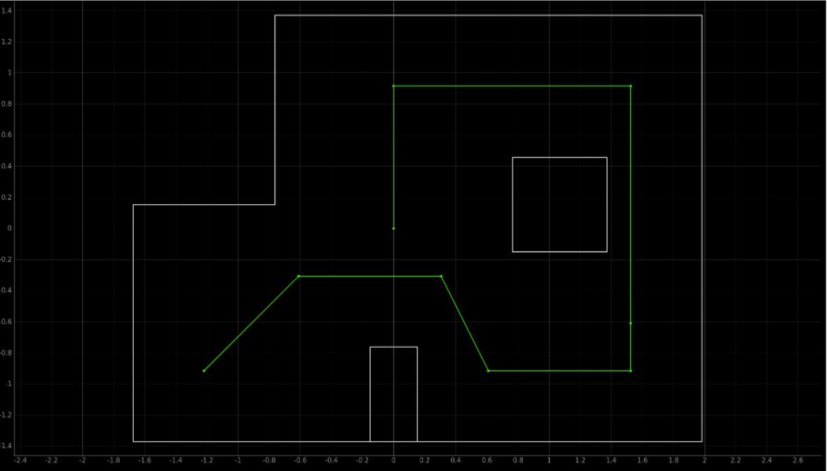
Lastly, these two motions were combined into a control file, which steps through each waypoint and their respective linear motions. This results in a trajectory closely matching the trajectory shown below:

Figure 2: Desired Robot Trajectory
The robot was succesfully able to complete this trajectory, and navigated to the following waypoints:
(-4, -3)
(-2, -1)
(1, -1)
(2, -3)
(5, -3)
(5, -2)
(5, 3)
(0, 3)
(0, 0)
4. Results
The resulting run from in the lab environment is shown below:
Final Demo Video - Waypoint Navigation
5. Final localization
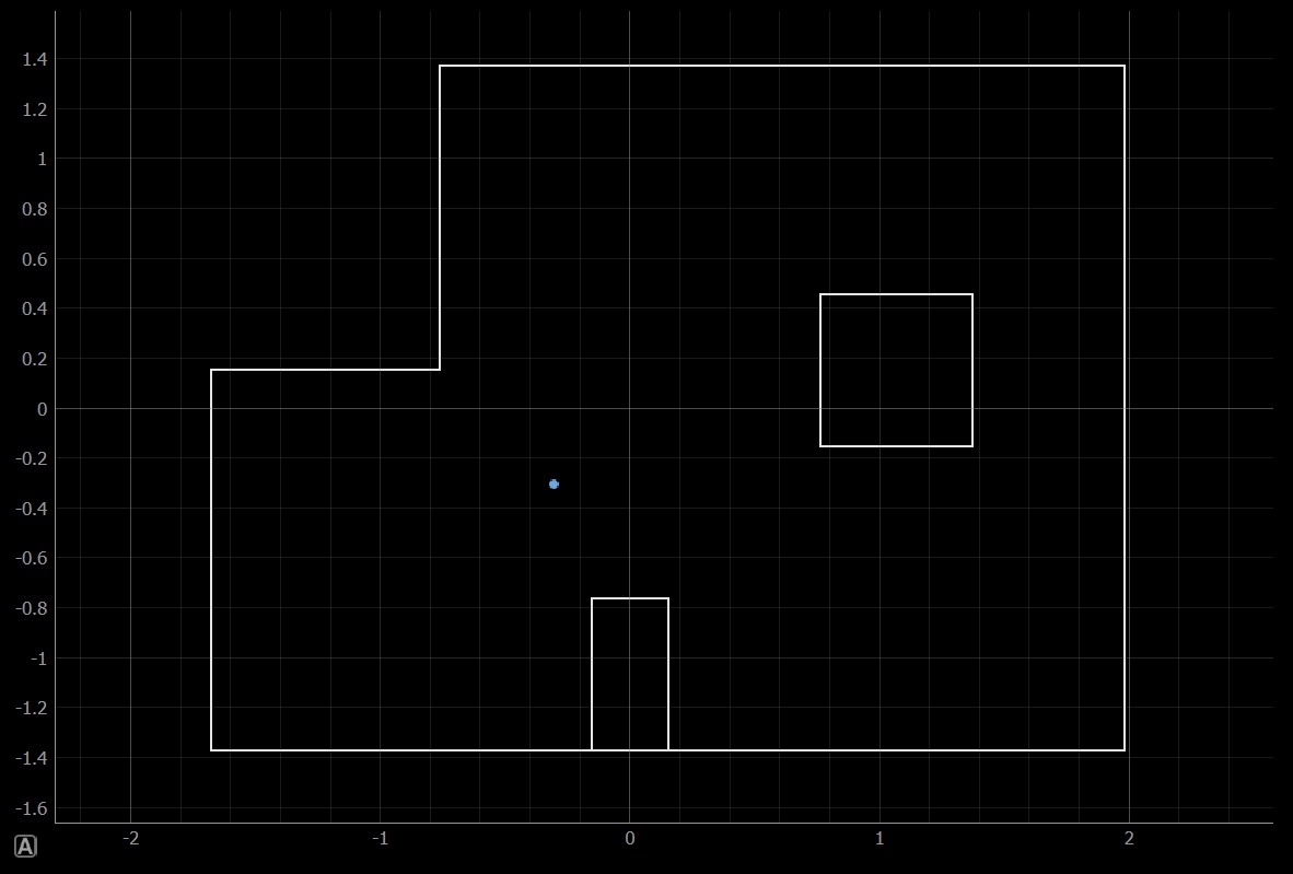
A localization rotation is done at the very end of the trajectory to ensure that the robot indeed did reach its destination. The output (this is the same algorithm as was developed for lab 12) is shown below. It is not perfectly accurate and indicates its position as lower in the y-direction than anticipated, but is relatively correct.

Figure 3: Final localization of the robot
- - - - - This concludes Lab 12 - - - - -