ECE 4960: LAB 5 - Open Loop Control
Description
This lab was the first lab using code to control the robot instead of the manual remote control. The goal here was to create basic functions to calibrate and drive the motors forward. The result of this lab was the ability to execute a series of open loop pre-programmed moves with the robot.
1. Motor Driver PWM signals
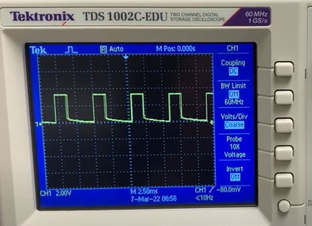
The first step was to wire up one motor driver to the Artemis, and power it from an external power supply to read the PWM signals with an oscilloscope. Below is the oscilloscope output of a motor driver being ran at a PWM value of 80. As can be seen From the oscilloscope plot, there is a clear duty cycle regulating the output power from the motor driver:

Figure 1: Motor Driver Oscilloscope Output
2. Spinning One Motor with the Motor Driver
Next, we were supposed to hook up a first motor to the motor driver, and use a power supply to rotate one set of wheels. Given time constraints, I proceeded to wire up the robot with the battery directly, and soldered the motors to the motor driver. Below is an example of one set of wheels rotating at a duty cycle of 70, indicating that the motor driver indeed is wired up well.
Rotating one Motor with the Artemis
3. Wiring up and Spinning both motors
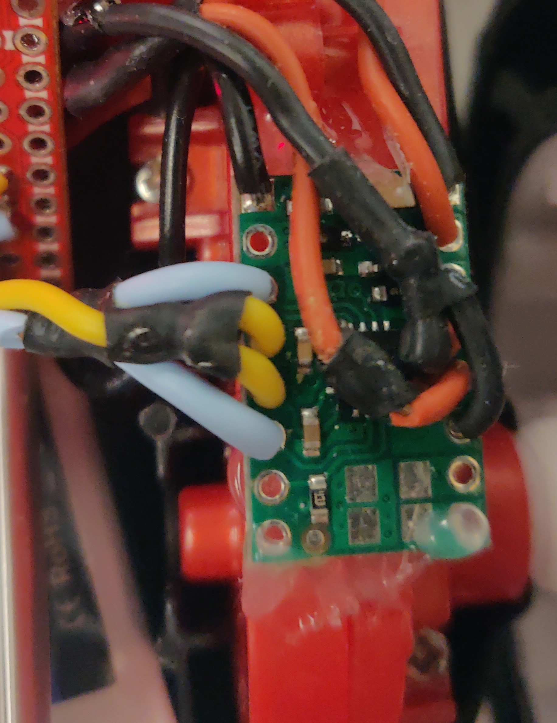
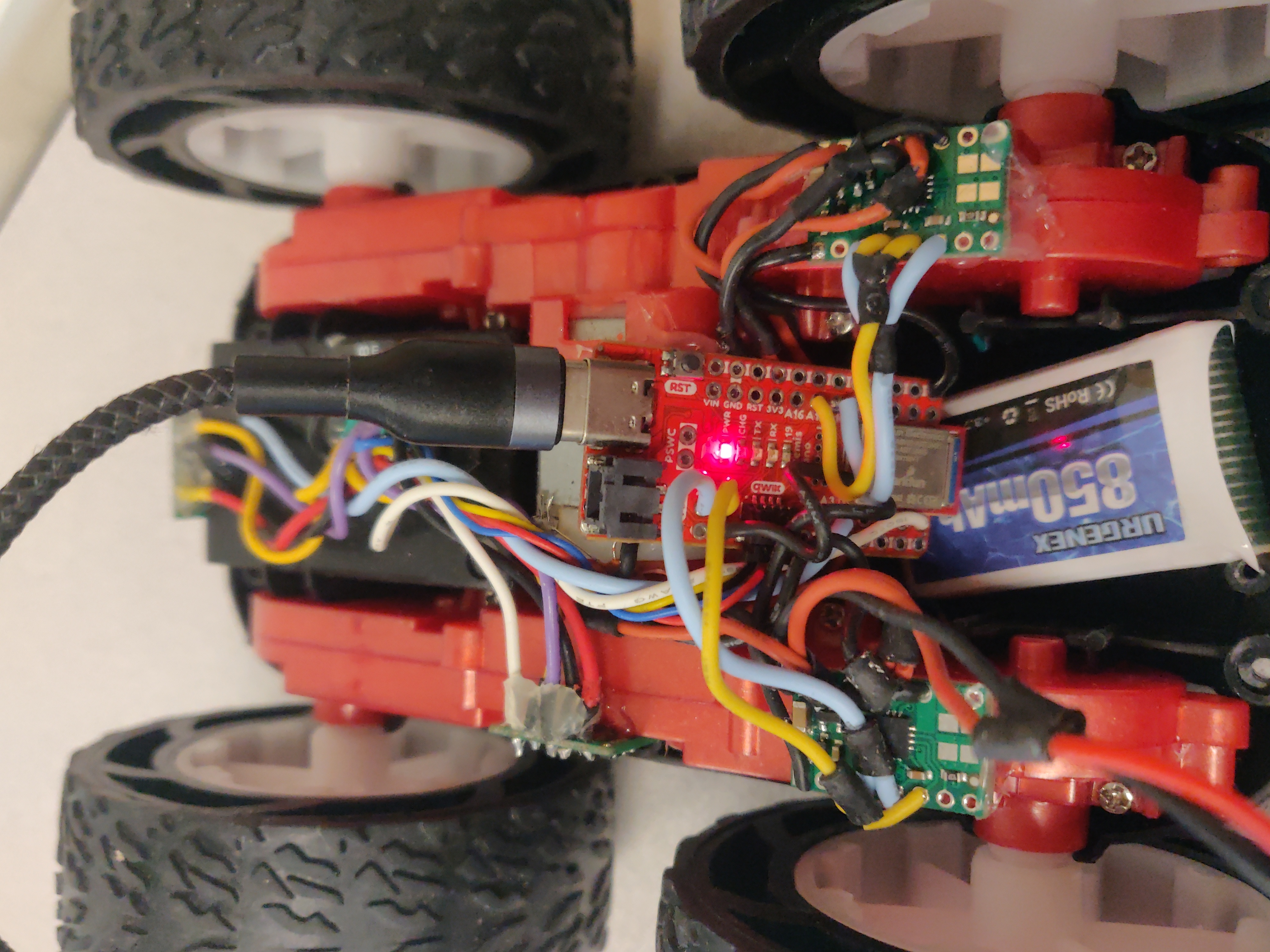
With one motor driver now functioning, i proceeded to wire up the second motor driver and attach everything in place in the chassis. A significant amount of time was spent soldering this step, since it involved connecting multiple terminals together which I found quite difficult to get right. Eventually, all motor drivers were soldered and glued to the car chassis:

Figure 2: Wiring for one Motor Driver

Figure 3: Wiring for both motor drivers
This resulted in full functionality in both directions for both motor drivers. Actuation of both of these is shown in the video below, where likewise the motors are being spun at a PWM duty cycle of 70, and are being rotated backwards and forwards.
Rotating both motors
4. Running the car on the ground & Calibration
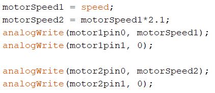
Next came the step of running the car on the ground. Here, I quickly realized that the motors were not calibrated, as mentioned in the lab handout. After some testing, I found that in order for the car to drive straight, one motor had to be ~2.1 times faster than the other motor. This resulted in the following driver code:

Figure 3: Motor Driver Calibration
With the motors now being calibrated, I was able to experiment whether the calibration performed as expected by having the robot drive in a straight line on the ground. The motor calibration shown above seemed to work, and at a relatively rapid speed (analogWrite parameter set to 70), the robot was able to execute a mostly straight path.
Calibrated Straight Path
5. Motor Lower Limit
A next step was to determine the lower PMW limit at which motors can rotate while still overcoming the force of friction. After several experiments, this lower limit turned out to be 25. Below this value, the motors no longer turn if the robot is placed on the ground. This will be important for future labs where the robot will have to determine its duty cycle on its own, but still move when the duty cycle is set to a value below this lower limit.
Lower Limit Demonstration
6. Open Loop Control
Finally, with the motors now calibrated, set up, and lower limit determined, it was time to demonstrate a series of random open loop motions. I made the robot rotate, drive, rotate again, etc. to show that all functionalities are working. This is shown in a final video below:
Open Loop Control
- - - - - This concludes Lab 5 - - - - -